E Series Valves and Manifolds
General Features
Flange Connections
According to DIN EN 61518 the manifold-transmitter interface is applicable for a max. allowable (Working) Pressure (PS) of 413 bar*3 (6,000 psi) and a maximum allowable Temperature (TS) of 120°C (248°F) for liquids, gas or vapors. The maximum allowable Temperature (TS) of 120°C (248°F) is considering the requirement that manifolds and transmitters need to be protected against heating by hot media. This can be achieved by using adequate hook-ups or by instrument impulse lines with sufficient length. However the AS-Schneider E Series Manifolds can be used for temperatures up to 550°C (1,022°F), PTFE up to 232°C (450°F), Graphite up to 550°C (1,022°F).
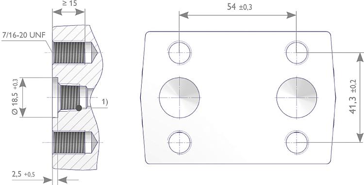
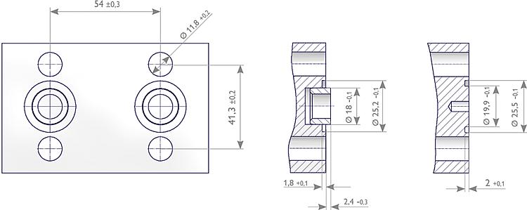
Flange Connections - Inlet Manifold respectively Transmitter Connection DIN EN 61518 / IEC 61518
1) Threaded Option for Transmitters - plug / vent valves
Type AType B |
| Connection at the manifold acc. to IEC 61518 / DIN EN 61518 *1 / *3 | |||||
| Type A with spigot | Type B without spigot | ||||
| Max. allowable (Working) Pressure (PS) |
413 (6.000) *3 | 413 (6.000) *3 | |||
| Temperature range in °C (°F) |
-10 to +80 (+14 to +176) |
-15 to +120 (+5 to +248) |
-40 to +120 (-40 to +248) |
-10 to +80 (+14 to +176) |
-40 to +120 (-40 to +248) |
| Seal Ring *2 | Flat Ring 24 x 17,7 x 2,7 Material: PTFE |
O-Ring ISO 3601-1 20 x 2,65 S-FPM90 Material: FPM (FKM by ASTM) |
Flat Ring 25,1 x 18 x 2,9 Material: Graphite |
Flat Ring 25,4 x 20 x 2,7 Material: PTFE |
Flat Ring 25,4 x 19,9 x 2,9 Material: Graphite |
| Min. thread engagement in mm |
9 | 9 | |||
1) DIN EN 61518 / IEC 61518: Mating dimensions between pressure measuring instruments and flanged-on shut-off devices
up to 413 bar (6,000 psi).
2) Materials and temperature limits for the flat rings and the O-Rings are for reference only. It is the responsibility of the user
to ensure compatibility between the selected gasket ring material and the process requirements, such as pressure, temperature,
and chemical compatibility.
3) IEC 61518 is stating 413 bar (6,000 psi), AS-Schneider however confirms 420 bar (6,092 psi).


